SMT vs Through-Hole: Choosing the Right Assembly Method for Your PCB Design
Heros Rising
When designing printed circuit boards (PCBs), one of the most critical decisions engineers face is selecting the appropriate component assembly method. The two dominant techniques—Surface Mount Technology (SMT) and Through-Hole Technology (also known as Plated Through-Hole or PTH)—each offer distinct advantages and limitations. At SUNTOP Electronics, a leading PCB assembly manufacturer, we understand that choosing between these methods impacts not only the functionality and reliability of your final product but also its manufacturability, cost, and time-to-market.
In this comprehensive guide, we’ll explore the technical differences between SMT and through-hole assembly, compare their performance across various metrics, and provide practical guidance on when to use each method. Whether you're developing consumer electronics, industrial controls, or high-reliability medical devices, understanding these core assembly technologies will empower you to make informed decisions during your PCB design phase.
Understanding Surface Mount Technology (SMT)
What Is SMT?
Surface Mount Technology (SMT) is a method of mounting electronic components directly onto the surface of a PCB without requiring leads to pass through holes. Developed in the 1960s and widely adopted by the 1980s, SMT revolutionized electronics manufacturing by enabling smaller, lighter, and more densely packed circuit boards.
Unlike traditional through-hole components, which feature wire leads that extend through drilled holes in the board, SMT components—commonly referred to as “chip components”—have flat terminals or small leads designed to be soldered directly to copper pads on the PCB surface.
How SMT Assembly Works
The SMT process involves several precise steps:
- Solder Paste Application: A stencil is aligned over the bare PCB, and solder paste—a mixture of tiny solder particles and flux—is applied to the pads where components will be placed.
- Component Placement: Using high-speed pick-and-place machines, SMT components are accurately positioned on the solder paste-coated pads.
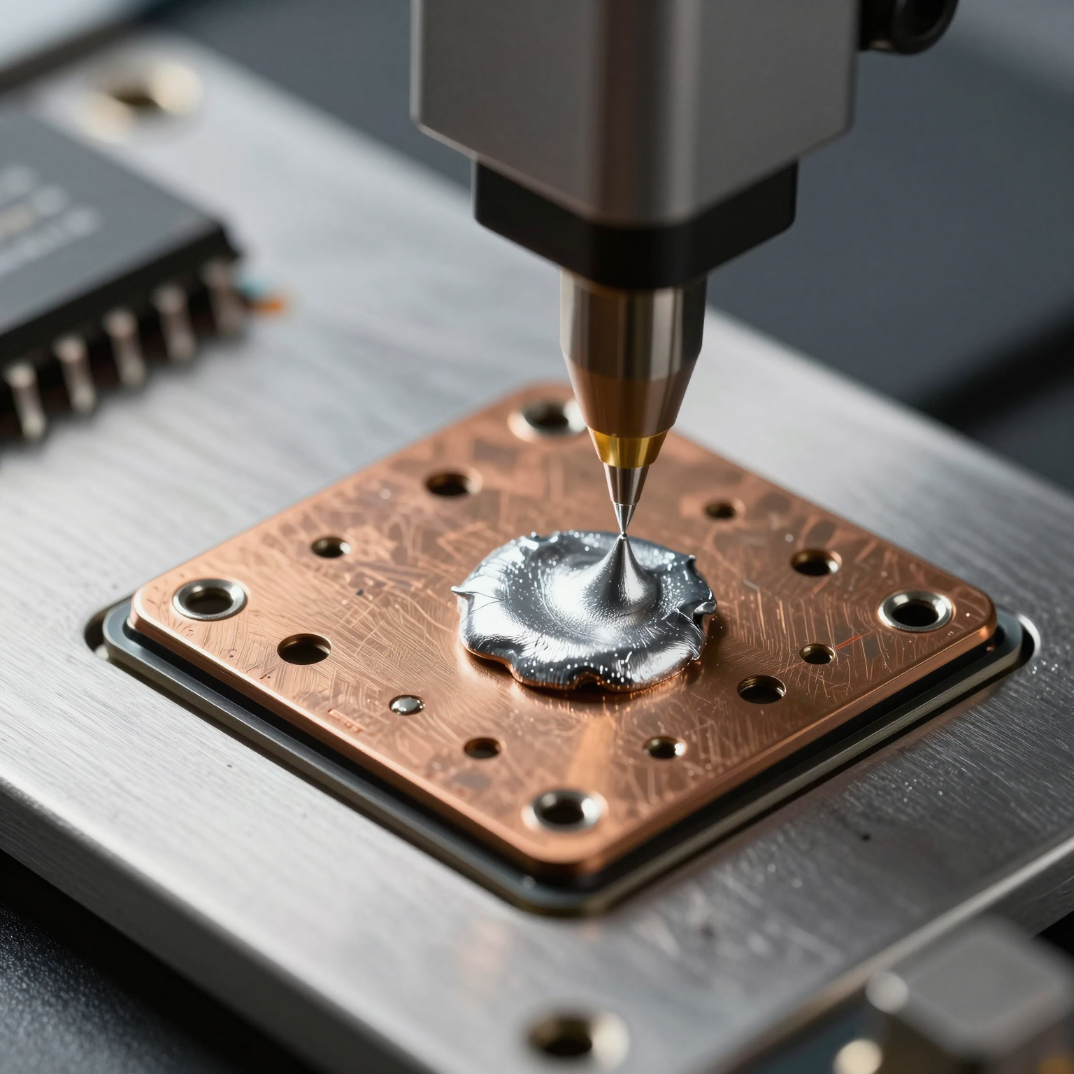
- Reflow Soldering: The board passes through a reflow oven, where controlled heat melts the solder paste, forming permanent electrical and mechanical connections.
- Inspection and Testing: Automated Optical Inspection (AOI), X-ray inspection (for hidden joints like BGAs), and functional testing ensure quality and reliability.
This automated workflow allows for rapid production of complex boards with thousands of components per hour, making SMT ideal for mass production environments.
Advantages of SMT
SMT has become the standard in modern electronics for good reason. Its benefits include:
- Smaller Footprint: Components can be placed on both sides of the board, significantly increasing component density.
- Higher Circuit Speeds: Shorter leads reduce parasitic inductance and capacitance, improving signal integrity at high frequencies.
- Lower Material Costs: No need for drilling numerous holes reduces fabrication complexity and cost.
- Automated Manufacturing: High compatibility with automated assembly lines increases throughput and consistency.
- Lightweight Design: Ideal for portable and wearable electronics where size and weight are critical.
For example, smartphones, tablets, and IoT devices rely almost entirely on SMT due to space constraints and performance demands.
Common SMT Component Types
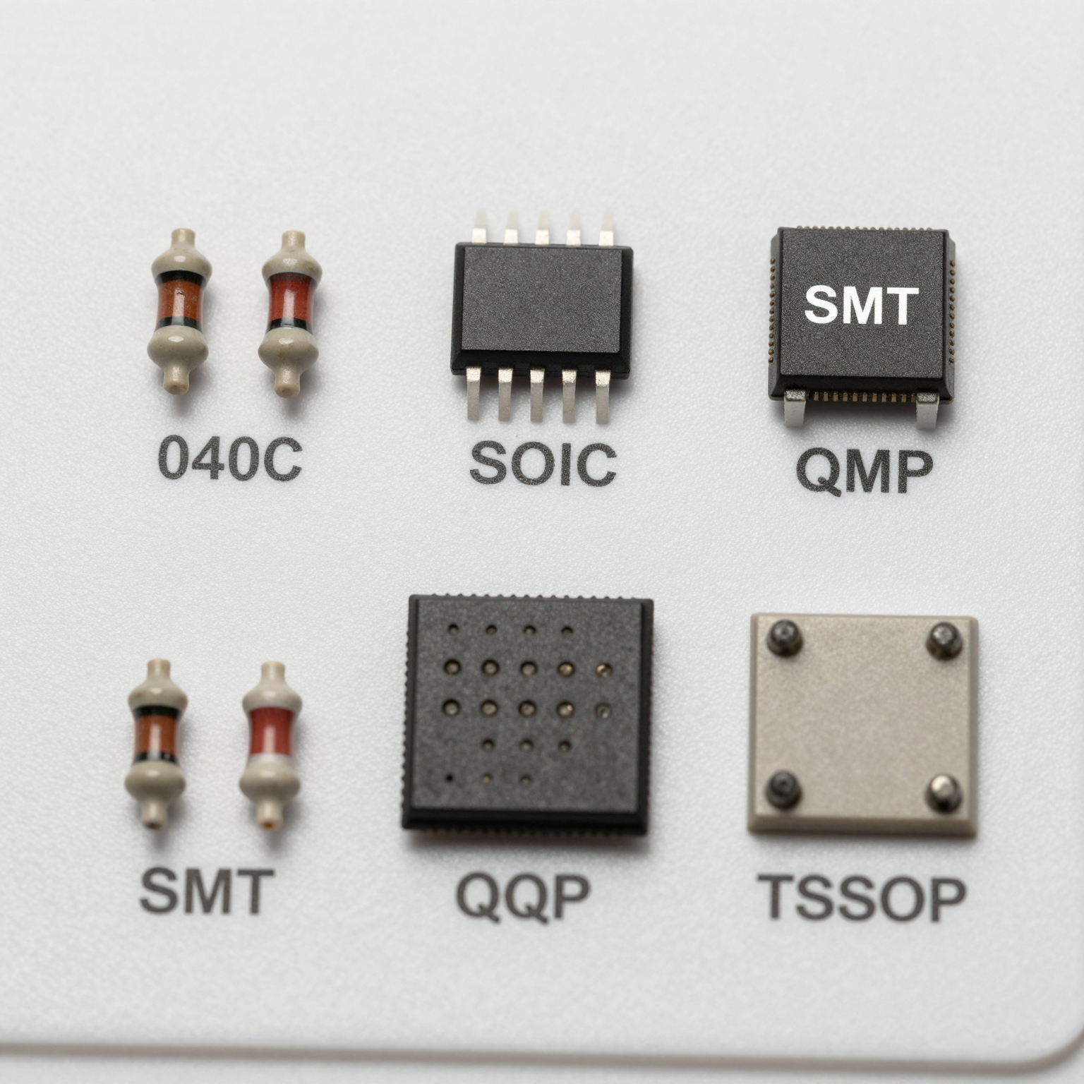
Some typical SMT packages include:
- Chip Resistors/Capacitors (0402, 0603, etc.)
- Small Outline Integrated Circuits (SOIC)
- Quad Flat Packages (QFP)
- Ball Grid Arrays (BGA)
- Thin Shrink Small Outline Packages (TSSOP)
These components enable advanced functionalities in compact form factors, supporting innovations in AI, 5G, and edge computing.
Did you know? Over 75% of all PCBs produced today use SMT exclusively or in combination with through-hole technology.
Exploring Through-Hole Technology (PTH)
What Is Through-Hole or Plated Through-Hole (PTH)?
Through-Hole Technology, often called Plated Through-Hole (PTH), involves inserting component leads through pre-drilled holes in the PCB and then soldering them on the opposite side. This method was the industry standard before the rise of SMT and remains relevant in applications demanding robust mechanical bonds.
Each hole is plated with copper to create an electrical connection between layers, hence the term “plated through-hole.” Components used in this method are typically axial or radial leaded types such as electrolytic capacitors, transformers, and connectors.
How PTH Assembly Works
The PTH assembly process includes:
- Drilling Holes: Precision drilling creates holes corresponding to component lead locations.
- Plating: Electroless copper plating ensures conductivity through the via walls.
- Component Insertion: Leads are inserted manually or via automated insertion machines.
- Wave Soldering: The board passes over a wave of molten solder
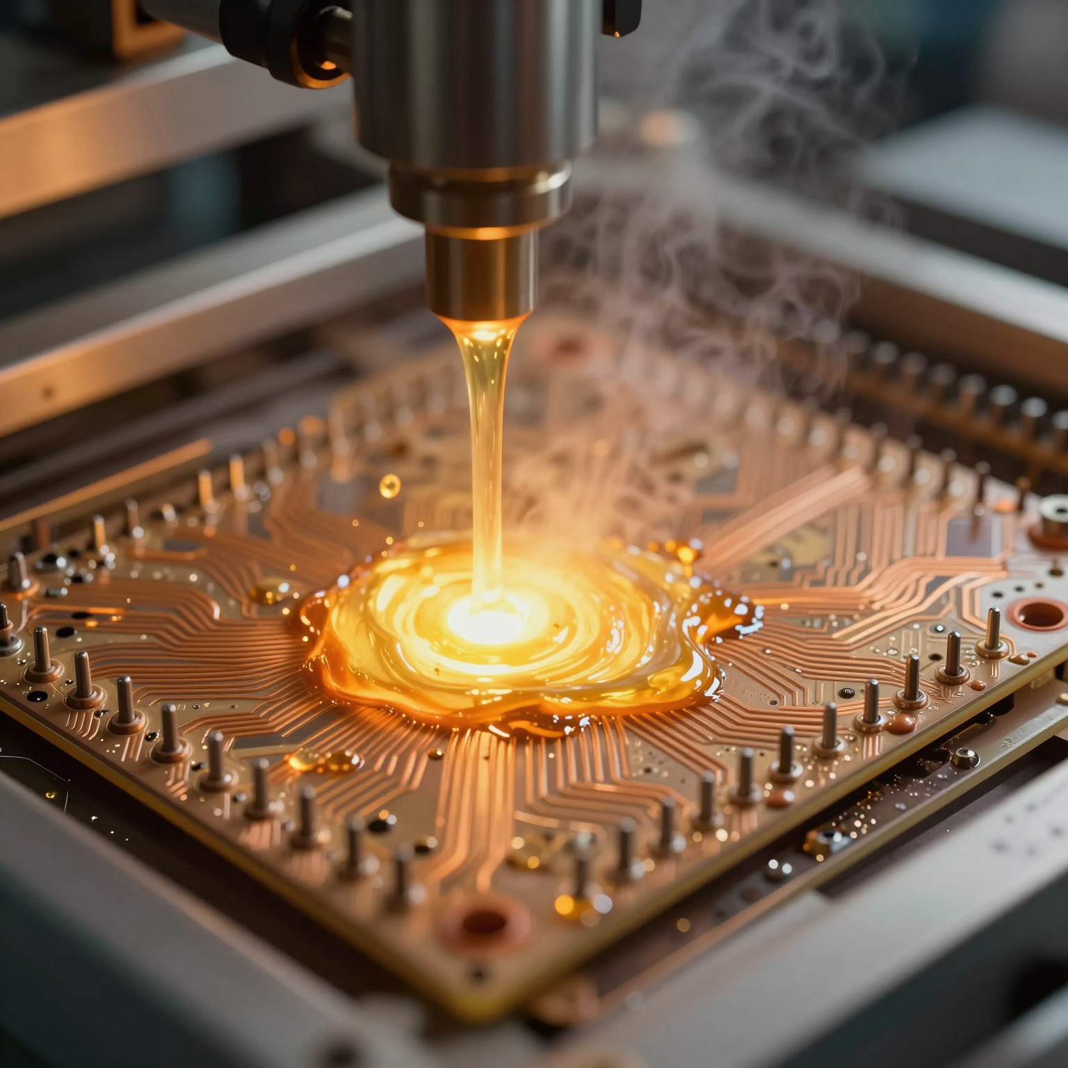
, which wets the exposed leads and pads, creating strong solder joints. 5. Manual Touch-Up and Inspection: Due to lower automation rates, manual checks and corrections are often required.
While slower than SMT, PTH offers unmatched durability in harsh environments.
Advantages of Through-Hole Components
Despite being older, PTH continues to serve vital roles because of its unique strengths:
- Superior Mechanical Strength: Components are physically anchored through the board, making them resistant to vibration, shock, and thermal stress.
- High Power Handling: Larger leads and better heat dissipation allow PTH parts to manage higher currents and voltages.
- Ease of Prototyping and Repair: Ideal for breadboarding and hand-soldering during development phases.
- Reliable Connections: Strong solder joints minimize failure risk in mission-critical systems.
Industries such as aerospace, defense, automotive, and heavy machinery still depend heavily on PTH for power supplies, relays, and ruggedized connectors.
Common Applications of PTH
Examples of components best suited for through-hole mounting include:
- Power Transistors and MOSFETs
- Large Electrolytic Capacitors
- Transformers and Inductors
- Terminal Blocks and Headers
- High-Pin-Count Connectors
These components benefit from the structural support provided by passing leads through the board.
Key Differences Between SMT and Through-Hole (PTH)
To help you decide which method suits your project, let’s compare SMT and PTH across several key parameters.
1. Size and Density
| Parameter | SMT | PTH |
|---|---|---|
| Component Size | Ultra-small (e.g., 0201 chips) | Larger, leaded components |
| Board Space Usage | Minimal; allows double-sided placement | Requires more space due to hole clearance |
| Component Density | Very high | Moderate to low |
SMT enables miniaturization essential for modern consumer electronics. For instance, a single smartphone motherboard may contain over 1,000 SMT components in less than 100 cm².
2. Electrical Performance
| Parameter | SMT | PTH |
|---|---|---|
| Signal Integrity | Excellent at high frequencies due to shorter paths | Longer leads increase inductance, affecting RF performance |
| Parasitic Effects | Low | Higher due to lead length |
| Impedance Control | Easier to achieve with controlled trace routing | More challenging due to component leads acting as antennas |
For high-speed digital circuits and RF applications, SMT is clearly superior. Engineers working on 5G modules or Wi-Fi 6E routers must prioritize SMT to maintain signal fidelity.
3. Mechanical Reliability
| Parameter | SMT | PTH |
|---|---|---|
| Vibration Resistance | Good with proper underfilling | Excellent due to through-board anchoring |
| Thermal Cycling Endurance | Moderate; depends on joint design | High; handles repeated expansion/contraction well |
| Shock Tolerance | Lower unless reinforced | Superior; ideal for military-grade equipment |
In automotive under-hood electronics or avionics, where extreme conditions prevail, PTH often remains the preferred choice despite size penalties.
4. Cost Considerations
| Parameter | SMT | PTH |
|---|---|---|
| Fabrication Cost | Lower (fewer/no drilled holes) | Higher (drilling adds time and wear) |
| Assembly Cost | Lower at scale (automated) | Higher (manual labor or specialized inserters) |
| Tooling Cost | Moderate (stencils, feeders) | High (drill bits, wave solder fixtures) |
| Rework Cost | Moderate to high (especially BGA) | Lower (easier access and desoldering) |
While SMT wins in volume production, PTH can be more economical for low-volume prototypes or repair scenarios.
5. Production Speed and Scalability
| Parameter | SMT | PTH |
|---|---|---|
| Placement Speed | Thousands of components per hour | Hundreds per hour |
| Automation Level | Fully automated lines possible | Partial automation; often hybrid setups |
| Suitability for Mass Production | Excellent | Limited |
Modern SMT lines can populate and solder a complete board in minutes, whereas PTH assembly requires additional handling and processing steps.
Hybrid Approaches: Combining SMT and PTH
In practice, many PCBs utilize a mixed-technology approach—leveraging the strengths of both SMT and PTH. This hybrid strategy allows designers to optimize for performance, reliability, and cost simultaneously.
Why Use Both Methods?
Consider a power supply unit (PSU):
- Control ICs, resistors, and capacitors are mounted using SMT for compactness and speed.
- High-current inductors, bridge rectifiers, and terminal blocks use PTH for thermal and mechanical stability.
By combining both, engineers achieve a balanced solution that meets electrical, environmental, and economic requirements.
Manufacturing Challenges in Mixed Assembly
Producing hybrid boards introduces logistical complexities:
- Sequential Processing: Boards usually go through SMT first, followed by PTH.
- Thermal Management: Reflow temperatures for SMT must not damage already-installed PTH components.
- Adhesive Staking: To prevent SMT parts from falling off during wave soldering, adhesives may be used to secure them before PTH processing.
At SUNTOP Electronics, our flexible PCB assembly services accommodate mixed-technology builds with optimized workflows that ensure yield and reliability.
Real-World Example: Industrial Motor Controller
An industrial motor controller might include:
- Microcontroller and logic circuits → SMT
- Gate drivers and optocouplers → SMT
- Power relays and heatsinked transistors → PTH
- AC input/output terminals → PTH
This blend ensures precision control while enduring high current loads and factory-floor vibrations.
Factors Influencing the Choice Between SMT and PTH
Selecting the right assembly method isn’t just about preference—it’s a strategic engineering decision influenced by multiple factors.
1. Application Environment
Harsh environments demand robust construction:
- Military/Aerospace: Prefer PTH for shock resistance.
- Consumer Electronics: Favor SMT for size and cost.
- Medical Devices: Often combine both for reliability and miniaturization.
- Automotive: Use SMT for ECUs, PTH for engine compartment sensors.
Environmental qualification tests (e.g., MIL-STD-810, ISO 16750) guide material and assembly choices.
2. Power Requirements
High-power circuits generate heat and require stable connections:
- Below 1A: SMT sufficient
- Above 5A: PTH recommended or hybrid with heatsinking
Thermal vias and copper pours can enhance SMT heat dissipation, but physical anchoring remains crucial for large power devices.
3. Frequency and Signal Speed
For analog and RF designs:
- Frequencies > 100 MHz: SMT preferred
- High-speed digital (USB 3.0, PCIe): SMT mandatory
- Low-frequency control signals: PTH acceptable
Impedance matching and controlled impedance traces are easier to implement with SMT components.
4. Volume and Production Scale
- Prototypes & Low-Volume (<100 units): PTH easier for hand assembly
- Medium Volume (100–10k units): Hybrid or SMT with selective PTH
- High Volume (>10k units): SMT dominates for efficiency
Tooling investment favors SMT in large runs, while setup simplicity benefits PTH in small batches.
5. Lifecycle and Maintenance Needs
Products expected to undergo field servicing benefit from PTH:
- Field-replaceable fuses, connectors, or switches
- Educational kits and DIY electronics
- Legacy system upgrades
SMT components, especially micro BGAs, are difficult to replace without specialized tools.
Design Tips for Optimizing SMT and PTH Selection
Effective PCB design starts with early consideration of assembly methodology. Here are actionable tips to guide your selection.
1. Start with Functional Block Diagrams
Break down your circuit into functional blocks:
- Power stage → likely PTH
- Digital processing → definitely SMT
- Interface/connectivity → evaluate per connector type
This modular thinking simplifies trade-off analysis.
2. Prioritize Component Availability
Check component datasheets for package options:
- Many ICs now only come in QFN or BGA (SMT-only)
- Some legacy parts exist only in DIP (dual in-line package) format
Avoid designing around obsolete PTH-only components unless necessary.
3. Plan for Testability
Ensure test points are accessible:
- SMT test pads should be ≥0.9 mm diameter
- Avoid placing PTH components where they block probe access
Design for in-circuit testing (ICT) and boundary scan (JTAG) early.
4. Consider Thermal Management
For power-dissipating components:
- Use thermal vias under SMT pads
- Provide adequate copper area
- For very high heat, consider PTH with external heatsinks
Simulation tools like thermal FEA help predict hotspots.
5. Collaborate Early with Your Manufacturer
Engage your PCB assembly manufacturer during the design phase. At SUNTOP Electronics, we offer design for manufacturability (DFM) reviews to catch potential issues before production.
Common pitfalls we identify:
- Misaligned footprints
- Insufficient solder mask dams
- Missing polarity markings
- Incorrect stencil thickness
Early feedback saves time and money.
Future Trends: Where Are SMT and PTH Headed?
Technology evolution continues to shape the landscape of PCB assembly.
Miniaturization Drives SMT Innovation
Trends include:
- Ultra-fine pitch components (0.3 mm spacing)
- Wafer-level packaging (WLP)
- Embedded components within substrate layers
HDI (High-Density Interconnect) boards increasingly integrate passive components beneath ICs, pushing SMT capabilities further.
Learn more about next-gen trends in our article on HDI PCB technology.
PTH Niche Consolidation
While declining in mainstream use, PTH retains strongholds in:
- High-voltage systems (industrial, energy)
- Ruggedized communications gear
- Legacy infrastructure maintenance
New materials like conductive epoxies may eventually supplement or replace some PTH applications, but full obsolescence is unlikely soon.
Emerging Hybrid Techniques
Innovations such as:
- Selective soldering robots for PTH after SMT
- Laser-assisted rework stations
- Conformal coating integration
are enhancing hybrid board reliability and scalability.
Additionally, advancements in electronic component sourcing and supply chain resilience are helping manufacturers adapt quickly to part shortages—a growing concern post-pandemic.
Why Partner with SUNTOP Electronics?
At SUNTOP Electronics, we specialize in delivering high-quality, reliable PCB solutions tailored to your specific needs. As a trusted PCB assembly manufacturer, we offer end-to-end services—from initial concept and PCB design support to full-scale production and testing.
Our capabilities include:
- Advanced SMT lines with multi-head mounters
- Selective wave soldering for PTH components
- Full QA services including AOI, X-ray, and functional testing
- Comprehensive PCB quality testing protocols
We adhere to IPC-A-610 Class 2 and Class 3 standards, ensuring every board meets rigorous performance criteria.
Whether you're building a prototype or launching a global product line, our team provides expert guidance on selecting the optimal assembly method—SMT, PTH, or hybrid—to match your technical and business goals.
Ready to bring your next project to life? Get a PCB quote today and discover how SUNTOP Electronics can support your innovation journey.