Mastering Circuit Board Assembly: Process, Tips & Best Practices
Winnie King
In today’s rapidly evolving electronics industry, Circuit Board Assembly is a cornerstone of modern device production. Whether you're developing consumer gadgets, medical devices, or industrial automation systems, the quality and reliability of your printed circuit board (PCB) directly impact performance and longevity. This guide dives deep into the Circuit Board Assembly process, covering everything from standard Rigid Circuit Board Assembly to advanced **HDI Circuit Board Assembly
** and **Flexible Circuit Board
** integration. We’ll also share essential tips to ensure success in your next electronics project.
What Is Circuit Board Assembly?
Circuit Board Assembly, often abbreviated as PCBA, refers to the process of mounting electronic components onto a bare printed circuit board. Unlike PCB fabrication—which involves creating the physical board with copper traces—assembly focuses on populating the board with resistors, capacitors, integrated circuits (ICs), connectors, and other parts that bring the circuit to life.
There are several types of boards used in this process:
- Rigid Circuit Board Assembly: The most common type, made from solid substrate materials like FR-4.
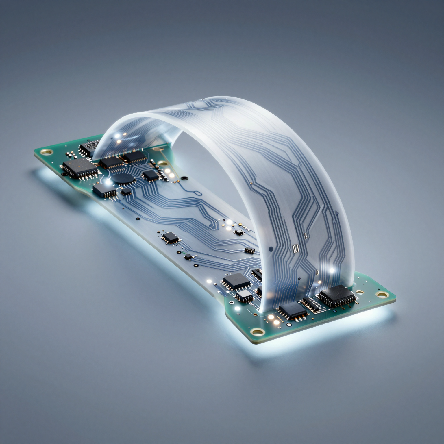
- Flexible Circuit Board: Made from pliable polymer films such as polyimide, allowing bending and folding.
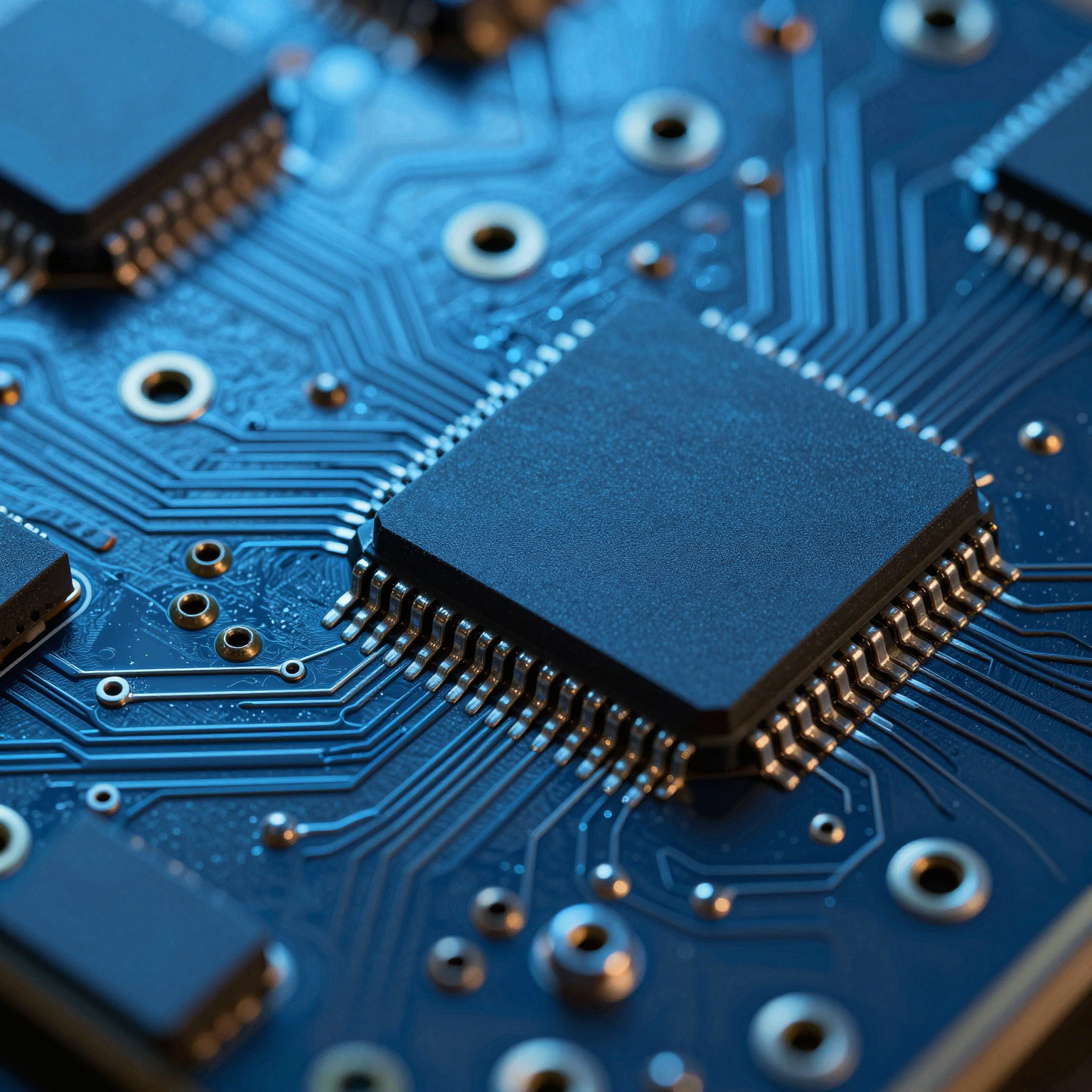
- HDI Circuit Board Assembly: High-Density Interconnect boards featuring finer lines, smaller vias, and higher connection density.
Each variant serves unique applications, but all follow a structured assembly workflow designed for precision and repeatability.
The Circuit Board Assembly Process: Step by Step
Understanding the full lifecycle of Circuit Board Assembly helps engineers and product designers make informed decisions. Here’s a breakdown of the key stages:
1. Solder Paste Application
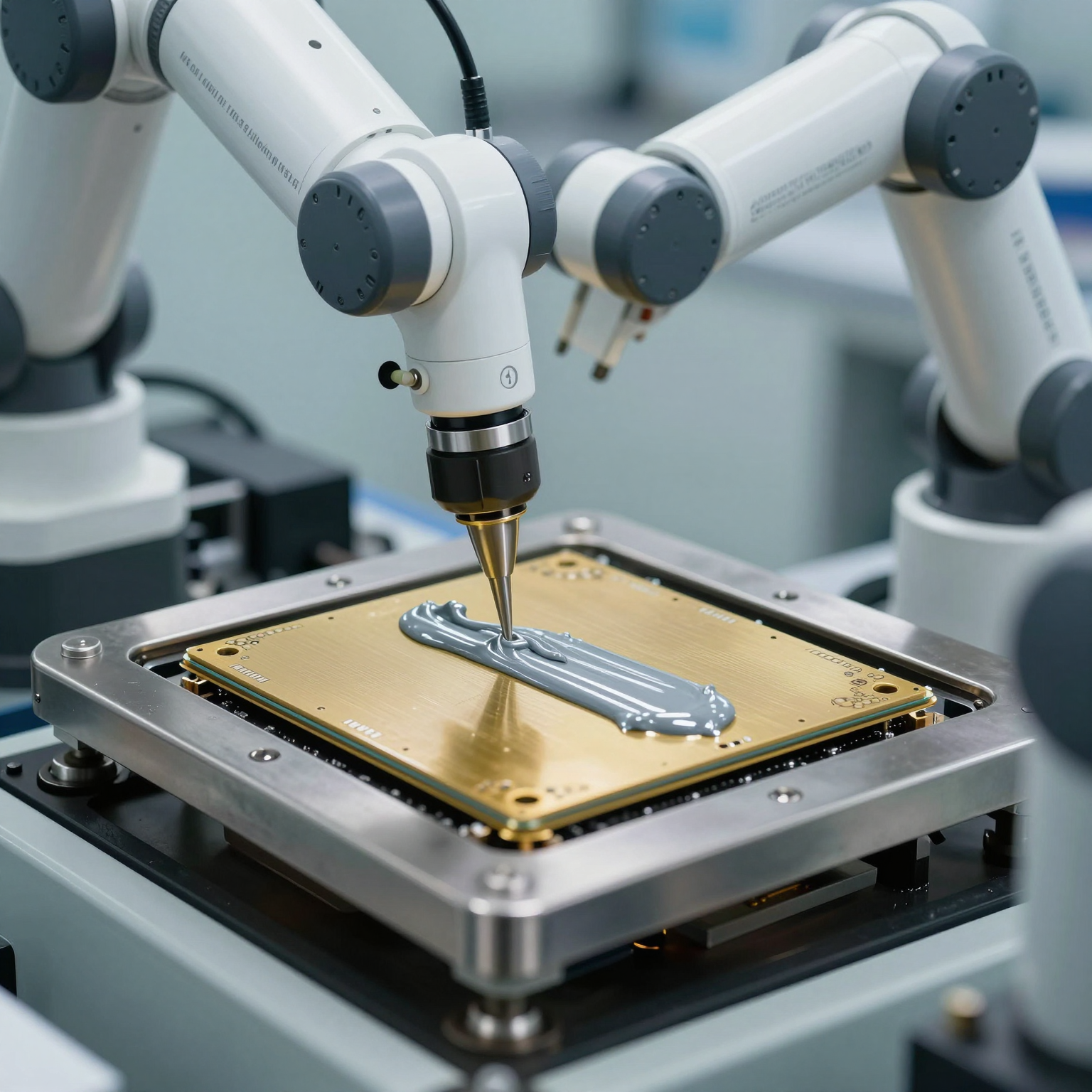
The first step in surface mount technology (SMT) assembly is applying solder paste to the PCB pads where components will be placed. A stainless steel stencil ensures precise deposition only on designated areas.
Solder paste is a mixture of tiny solder particles and flux, which cleans the metal surfaces during reflow and promotes strong electrical connections. Uniformity and accuracy at this stage are critical—too much or too little paste can lead to defects like bridging or tombstoning.
2. Component Placement
Once the paste is applied, automated pick-and-place machines position surface-mount components (SMDs) onto the board. These machines use vision systems to align components accurately, even for ultra-fine pitch ICs.
For complex designs involving HDI Circuit Board Assembly, component placement must account for tight spacing and microvias. Misalignment here can compromise signal integrity and thermal management.
Through-hole components are typically inserted later, either manually or via automated insertion equipment, depending on volume and complexity.
3. Reflow Soldering
After placement, the board enters a reflow oven where controlled heat melts the solder paste, forming permanent electrical and mechanical bonds. The temperature profile—ramp-up, soak, peak, and cool-down phases—must be carefully calibrated based on the components and board material.
For Flexible Circuit Board assemblies, special care is needed due to the lower thermal tolerance of polyimide substrates. Excessive heat can cause warping or delamination, so optimized profiles using nitrogen-enriched ovens are often employed.
4. Inspection and Testing
Post-soldering inspection is crucial for catching defects early. Automated Optical Inspection (AOI) checks for missing components, misalignments, solder bridges, and insufficient fillets.
X-ray inspection may be used for hidden joints, especially in HDI Circuit Board Assembly with buried vias or Ball Grid Array (BGA) packages. Functional testing then verifies that the assembled board operates according to design specifications.
Implementing a robust 6-step quality control process significantly improves yield rates and reduces field failures.
5. Through-Hole Assembly (If Required)
While many modern designs rely solely on SMT, some applications still require through-hole technology (THT) for high-reliability connections or larger components like transformers and connectors.
In THT, leads are inserted through drilled holes and soldered on the opposite side, usually via wave soldering or selective soldering. This adds time and cost but enhances durability in harsh environments.
For mixed-technology boards, the sequence matters: SMT components are generally processed first, followed by THT, to avoid damaging already-mounted parts.
6. Final Cleaning and Coating
Residues from flux and handling can affect long-term reliability, especially in humid or corrosive environments. Final cleaning removes contaminants, while conformal coating applies a protective layer (e.g., acrylic, silicone, or urethane) over the entire board.
This step is particularly important for Flexible Circuit Board applications exposed to moisture or vibration, such as wearable devices or automotive sensors.
Types of Circuit Boards in Assembly
Not all circuit boards are created equal. Choosing the right type depends on your application's mechanical, environmental, and performance requirements.
Rigid Circuit Board Assembly
Most consumer electronics use Rigid Circuit Board Assembly due to its stability, ease of manufacturing, and low cost at scale. These boards maintain their shape under stress and support dense component layouts.
Common uses include desktop computers, power supplies, and home appliances. However, they lack flexibility and cannot be used in compact or curved spaces.
Tip: Use standardized footprints and avoid overly tight clearances to reduce manufacturing complications.
Flexible Circuit Board
Flexible Circuit Board solutions enable innovative designs where space and weight are constraints. They can bend, fold, and twist, making them ideal for foldable smartphones, medical implants, and aerospace systems.
However, assembling flex boards presents challenges:
- Handling requires specialized fixtures to prevent damage.
- Registration marks must be clearly defined for accurate alignment.
- Stiffeners may be added to support heavy components.
Designers should follow flexible PCB design best practices to ensure manufacturability and reliability.
HDI Circuit Board Assembly
HDI Circuit Board Assembly supports miniaturization through technologies like microvias, blind/buried vias, and finer trace widths. HDI boards pack more functionality into smaller footprints—critical for smartphones, tablets, and IoT devices.
Key advantages:
- Improved signal integrity
- Reduced electromagnetic interference (EMI)
- Enhanced thermal performance
But HDI comes with tighter tolerances and higher costs. Manufacturing demands advanced imaging, laser drilling, and precise lamination processes.
To learn more about future trends, read our article on HDI PCB technology shaping next-gen electronics.
Essential Tips for Successful Circuit Board Assembly
Even with advanced machinery and skilled technicians, poor design choices can derail an otherwise smooth Circuit Board Assembly process. Follow these expert tips to improve outcomes:
1. Design for Manufacturability (DFM)
Always collaborate with your PCB assembly manufacturer early in the design phase. DFM reviews catch potential issues like inadequate spacing, non-standard hole sizes, or problematic component orientations before production begins.
Use recommended land patterns, adhere to minimum trace/space rules, and allow sufficient clearance around tall components for rework access.
2. Choose the Right Surface Finish
Surface finishes protect copper pads from oxidation and ensure good solderability. Common options include:
- HASL (Hot Air Solder Leveling): Cost-effective but not ideal for fine-pitch components.
- ENIG (Electroless Nickel Immersion Gold): Flat surface, excellent for BGAs and HDI.
- OSP (Organic Solderability Preservative): Simple and eco-friendly, but short shelf life.
For HDI Circuit Board Assembly, ENIG or immersion silver are preferred due to flatness and reliability.
Learn more in our comprehensive PCB surface finishes guide.
3. Optimize Panelization
When producing multiple small boards, panelization increases efficiency. For Flexible Circuit Board arrays, consider breakaway tabs or scoring lines for easy depaneling without damaging delicate circuits.
Avoid placing sensitive components near edges or routing channels to prevent stress cracks.
4. Implement Rigorous Testing Protocols
Don’t skip functional testing—even prototypes benefit from basic continuity and power checks. In-circuit testing (ICT) and flying probe tests verify individual components, while boundary scan (JTAG) helps debug complex digital systems.
Pair testing with data logging to track failure modes and refine future designs.
5. Partner with a Reliable Supplier
Component shortages and counterfeit parts plague the electronics supply chain. Work with a trusted partner offering transparent electronic component sourcing and traceability.
A reputable manufacturer will provide full documentation, including RoHS compliance, lot numbers, and test reports.
Explore how professional PCB assembly services streamline development and reduce time-to-market.
Emerging Trends in Circuit Board Assembly
The landscape of Circuit Board Assembly continues to evolve with new materials, processes, and integration techniques.
- Increased Adoption of Flex-Rigid Boards: Combining rigid and flexible layers in one assembly allows 3D packaging and eliminates connectors.
- Miniaturization via Embedded Components: Active and passive components embedded within the PCB substrate reduce footprint and improve performance.
- AI-Driven Quality Assurance: Machine learning algorithms analyze AOI and X-ray images faster and more accurately than humans.
- Sustainable Manufacturing: Lead-free solders, recyclable substrates, and energy-efficient processes are becoming standard.
Staying ahead means embracing innovation while maintaining rigorous quality standards.
Conclusion
Circuit Board Assembly is far more than just attaching parts to a board—it’s a sophisticated blend of engineering, precision, and quality control. Whether you're working with traditional Rigid Circuit Board Assembly, cutting-edge HDI Circuit Board Assembly, or innovative Flexible Circuit Board designs, understanding the full process empowers better decision-making.
By following best practices—from DFM and surface finish selection to partnering with experienced manufacturers—you can achieve high yields, superior reliability, and faster product launches.
Ready to bring your next electronics project to life? Explore our full range of PCB manufacturing services and discover how we support every stage of development—from prototype to mass production.